Where will the active electronically scanned array (AESA) radar go in the coming years?
Seemingly bucking the Cold War trend, it was neither the Soviet Union nor the United States who first brought AESA radars into service, although both nations poured significant investment into the technology during the Cold War. That distinction goes to Japan. The country’s Maritime Self Defence Force (JMSDF) introduced this electromagnetic game changer, in the form of the Mitsubishi OPS-24 L-band naval surveillance radar, on the HAMAGIRI – an ASAGIRI-class destroyer, in 1988. The first airborne AESA was Israel Aerospace Industries’ (IAI) EL/M-2075 PHALCON L-band airborne early warning (AEW) radar, deployed on an Israeli Air Force (IAF) Boeing 707 in 1994. The honour of the first ground-based AESA radar also goes to Japan: the Mitsubishi J/FPS-3 S-band air surveillance radar entered service with the Japan Air Self Defence Force (JASDF) in 1995.
AESA radars owe their development to the realisation of passive electronically scanned array (PESA) radars. Conventional radars employ a cavity magnetron to generate a radio signal. At the centre of a magnetron is a heated metal rod known as a cathode, which sits in the centre of a ring known as an anode. An electrical current is passed through the cathode causing it to heat up and, as it does so, electrons bubble off it like steam from a kettle, moving across the air gap between cathode and anode. The whole ensemble has clever ingredients in the form of cavities cut into the anode and a magnet placed beneath, which generates a magnetic field inside the assembly.
The electrons thus pass through an electronic field between the cathode and anode, and a magnetic field produced by the magnet. Rather than following a straight path, the magnet forces the electrons to move in a curved pattern, orbiting the cathode and, as they move past the cavities, they cause the cavities to vibrate, much like blowing across the top of an empty bottle will trigger a sound from the vibration. In this case, however, the resonance produces microwaves, which are then channelled via a waveguide into the radar’s antenna, which transmits them in a particular direction. The microwaves hit their targets and return to the transmitter as an echo.
Solid State
The advent of so-called solid state semiconductor electronics in the 1960s paved the way for the PESA radar, the term solid state betraying the key differences of this technology compared to the vacuum tube. Whereas the generation of microwaves occurs in the gaseous state inside a vacuum tube, a semiconductor employs an ingeniously simple principle: the physical properties of the material from which the semiconductor is constructed, such as quartz or silicone, will only allow electrons to move in one direction.
Solid state radars have several inherent benefits compared to vacuum tube radars: they typically boast greater reliability, as the need to replace worn-out tubes is dispensed with, and can tolerate higher operating temperatures, resulting in more powerful radars. A PESA radar takes its RF energy from a single source. This energy is passed through a phase shifter; a computer-controlled gate which splits the single source into several paths connected to individual transmitting elements positioned across an antenna. The clever thing about the phase shifter is that it can prevent all the RF energy being released at once, imposing a slight delay between each element transmitting its energy across the antenna. Like ripples on a pond, each RF wave has a spherical shape and, as the phase shifter moves from left to right, it artificially steers the radar’s transmissions in a particular direction.
Each wave collides with the previous one as it leaves the antenna, effectively knocking it in a particular direction, in this case to the left of the antenna’s axis. Similarly, this process can be reversed to steer a beam to the right or up and down. The advantage of the PESA is that it was no longer necessarily to physically move the antenna to have a wide field-of-view. This allowed a radar to scan its RF transmissions more rapidly across the sky, thus detecting targets faster than when the antenna had to be physically rotated. Moreover, several PESA antennae can be mounted on a structure to provide 360° of azimuth, negating the need for a rotating antennae. One of the most notable examples of a PESA system is Lockheed Martin’s AN/SPY-1 S-band naval surveillance radar, which entered service with the US Navy (USN) on its TICONDEROGA-class class cruisers in the early 1980s and remains in service today.
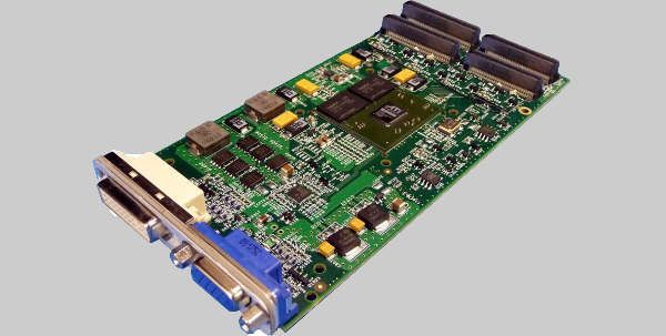
AESA radars have much in common with their PESA counterparts. Rather than the RF energy being generated at a single point and being fed through a phase shifter, an AESA antenna is comprised of hundreds of transmit/receive (TR) modules, each of which acts as a radar in its own right, generating and transmitting the RF and receiving the echoes. The ability to task these TR modules to perform different tasks provides AESA radars with advantages over PESA architecture. As a PESA generates all its RF at one point, all of its transmissions use same frequency, whereas the characteristics of the TR modules allow AESA radars to spread their transmissions across a number of frequencies, reducing the chances of the radar’s detection.
This ability allows an AESA to perform several different tasks simultaneously, such as general surveillance while tracking a ballistic missile, for example. The advent of the AESA prompted a paradigm shift in military radar design and deployment. Nevertheless, these radars have been in routine military service for three decades. Where does AESA technology go from here?
Cognitive Radar
The growth of AESA technology has moved hand-in-hand with improvements in signal processing. This has mirrored electronics innovation in the non-military domain; your cellphone can perform more tasks today than that of ten years ago, due to software improvements. The breakneck speed at which software innovation moves will have an impact in the radar domain, particularly in the field of Artificial Intelligence (AI). The online resource technopedia.com provides a good definition of AI: “The creation of intelligent machines that work and react like humans.” Key to this is the ability of the machine to learn lessons from its operations in the near and distant past and apply those to its current environment. So-called ‘Cognitive Radar’ could adapt elements of AI.
”Foundations of Cognitive Radar for Next-Generation Radar Systems,” written by Dr Nathan Goodman, a professor in electrical and computer engineering at Gallogly College of Engineering, University of Oklahoma and appearing in 2018 as a chapter in the Academic Press Library in Signal Processing Volume 7, offers a useful definition: “all radar systems constantly observe the surrounding environment, inferring properties about the environment based on observations and modifying their observation of the environment through changing waveforms and antenna pointing directions [but cognitive radar] maintains real-time hypotheses about the environment in order to adaptively control the form and parameters of the actual sensing procedure.”
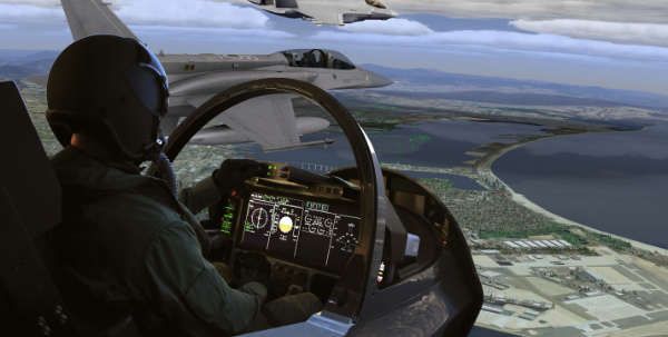
This means that a radar could begin to understand what it is seeing and tailor its behaviour according to the situation. For instance, a radar could be looking at a patch of ground on which several vehicles are moving in the same direction, possibly indicating a column of armoured vehicles. Meanwhile, nothing is happening in the rest of the territory in the radar’s gaze. In such a situation, the radar can concentrate its efforts on watching the column and place a lower priority on watching what is happening elsewhere:
“The more time a radar spends looking at an area of interest the better the information that can be derived from it becomes,” states Andy Nejman, Capability Manager for AESA Radar at Leonardo, However, he warns this can add greatly to operator workload, the solution to which is introducing a level of cognition into the radar, enabling it to understand what it is seeing: “A radar can readily produce a real-time picture of ground movements over a wide area, but it is the addition of intelligent exploitation software that provides a level of forensic analysis that converts this mass of data into useful information to the force commanders,” he explained. Nonetheless, the introduction of AI into radar technology brings its own challenges vis-à-vis data processing, due to the “vast increase in overall data bandwidth.” This will require “processing and data distribution architectures to evolve to match this demand.”
After GaN
Much has been made in the AESA domain of the advent of gallium nitride (GaN), a very hard semiconductor increasingly used in TR module construction. Highly resistant to heat and therefore capable of handling high power transmissions, it improves radar performance compared to legacy AESA T/R modules using gallium arsenide (AsGa). According to Sqn Ldr Ioannis Vagias, a lecturer in radar at the UK’s Defence Academy, “Cooling the (transmit) element is a challenge, especially with GaN amplifiers. So far, liquid cooling has been employed, with the coolant in some instances being corrosive to metals.”
Could such considerations cause GaN to be replaced? For this to occur, “the next wonder material will be something that either fulfils a requirement that renders current technology-based systems ‘insufficient’ or that reduces the manufacturing costs so dramatically that it creates a ‘spend to save’ case for industry to invest,” observes Mr Nejman. For Dan Kilfoyle, Technical Director and Principal Fellow of Raytheon’s electronic warfare systems division, there is still much mileage in GaN. “There’s still so much to be gained both in efficiency and power density. Like all technologies, the goal is smaller, faster and more affordable.”
A wonder material under consideration for the radar domain is diamond. Professor Hugh Griffiths, the Thales Royal Academy of Engineering chair of RF sensors at University College London, says that “people have talked about diamond for some time as its thermal conductivity is really good.”
This could translate into radars being able to tolerate even higher temperatures than GaN, thus pushing performance yet further.
Miniaturisation
Moore’s Law posits that the number of transistors on a single chip doubles every two years. This allows electronics to do more while taking up less space and is the reason today’s cellphone no longer resembles the boxlike constructs of the 1980s. Moore’s Law helped radar engineers cram the electronics which performed a radar’s functions onto individual TR modules. Prof Mathini Sellathurai, chair of signal processing at Herriot-Watt University, Edinburgh, believes the drive for miniaturisation will continue in radar design, arguing that electronics are moving into the nanotechnology domain. This may offer the ability to fit electronics into ever-decreasing spaces and could help further reduce a radar’s physical footprint. For example, the AN/SPY-1 radar has an all-up of 65,733kg: intelligent use of nanotechnology in radar design could help significantly reduce size and weight, not only for warships, but for platforms across the board.
Cost
Money is a perennial issue in defence procurement: equipment rarely seems to become less expensive and national defence budgets are always under pressure. Leonardo’s Nejman argues that ?I? “as much attention needs to be placed on the cost of manufacture as on the technical performance of an AESA radar system [….] while customers are always asking about the latest technology they have heard about, in practice what they really want is off the shelf, mature products that require no development [although the response] is to combine both these attributes: [….] this demands a roadmap that provides regular technology refreshment and a revenue stream that supports this investment.” ?P?
Next Steps
Embracing the world of civilian technology is one possible avenue for AESA evolution. Cost is a serious consideration for vendors and customers alike. The latter want a cost-effective radar, both in terms of procurement and service life and Nejman believes that watching technological developments in the telecommunications industry, in which RF components continue to advance, propelled by commercial demand for wireless technology, holds promise. Adopting technologies developed in this sector for military applications could help to reduce development costs. Similarly, moving towards so-called multifunctional arrays could herald advantages.
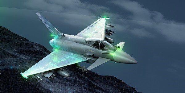
Combat aircraft radars have been traditionally located in the nose, with the jet’s electronic warfare and communications antennae positioned elsewhere. Multifunction arrays could see antennae being positioned around an aircraft; on its wings and fuselage, possibly in conformal arrays that following the contours of the fuselage. These could perform all of the jet’s RF functions as and when required. Such architectures are “being driven by the fighter radar market,” in Nejman’s view. He believes that, as this technology matures, it could equip other ‘RF heavy’ airborne platforms, such as maritime patrol aircraft.
However, Prof Griffiths believes that this will raise questions regarding scheduling, with the need to ensure that all sensors can be managed in such a way as to ensure the most important tasks – be that communications, radar or jamming – are prioritised. Perhaps the cognitive approach could assist? While he shares the opinion that tomorrow’s radars will employ distributed apertures and be increasingly networked, he cautions that this will require robust, wideband communications to be available on, and over, the battlefield, to handle the data generated by scores of federated radars on air, sea and land platforms. Ioannis Vagias agrees, saying that while we may see radar, communications, EW and even navigation and Identification Friend or Foe functions being blended together in a ‘system of systems’ approach using the same antennae, AI and cognition will be vital to manage this diverse array of tasks.
Another area to watch is frequency. In the radar domain, broadly speaking, there are trade-offs between radar range, antenna size and target resolution. Radars transmitting in the HF domain (3-30MHz) can detect targets at very long ranges, but at the expense of target resolution: they also require a large antenna to achieve this. Radars operating at higher frequencies, typically those in the millimetre waveband of 40-300GHz, can see targets in remarkable detail using a small antenna, but at the expense of range. For fighter radar engineers the Holy Grail would be to harness the power of such radars while retaining ranges in excess of the 180+km routinely achievable with X-band radars. Will this, and other such innovations, be realised in the next three decades of AESA evolution?
Dr Thomas Withington